Pits and vehicle hoists
Show pit edges, covers, hoist posts and operating envelopes. Review support conditions and do not assume a scaffold can bridge a pit or occupy a hoist area.

Fiberglass fleet access planning
Plan fiberglass access across bus maintenance bays. Review pits, vehicle hoists, columns, traffic routes, storage and complete platform footprints before selection.
Application overview
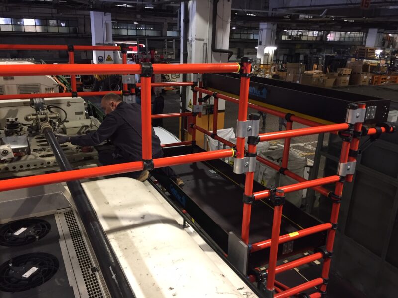
A fleet-bay access plan should address how the system arrives, is assembled, is used and leaves the work zone. Bus dimensions alone do not describe a workshop with pits, hoists, columns, extraction equipment and neighboring service tasks. Fiberglass platforms and towers can be evaluated within that full layout. The most useful specification separates the technician work area from the travel route, assembly space and storage footprint, then shows how each interacts with the fleet's vehicle-movement procedures.
Where it fits
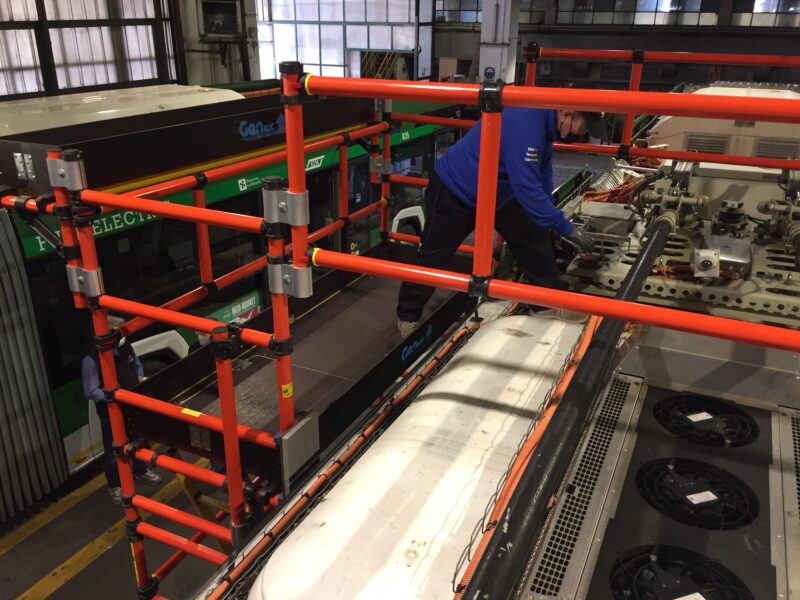
Real-world starting points for discussing the work, footprint and environment.
Show pit edges, covers, hoist posts and operating envelopes. Review support conditions and do not assume a scaffold can bridge a pit or occupy a hoist area.
Identify work that continues in the neighboring bay. Plan access so pedestrian routes, emergency exits and required service access remain available.
Trace the route through doors, turns and thresholds. Include storage arrangements for complete units or manufacturer-approved component packages.
Compare the constraints of every intended bay. A common configuration must fit the limiting conditions rather than only the largest or simplest bay.
Make a better decision
Use vehicle geometry, the maintenance sequence and the complete system requirements together.
Include the base, access method and required stabilization, not just the deck. Overlay that footprint on the vehicle and workshop plan before ordering equipment.
Separate vehicle arrival, positioning and departure from platform setup and use. Define who controls the work area and how access equipment is kept clear of moving vehicles.
Confirm floor and support conditions with the facility. Add equipment inspection, cleaning, component replacement and storage responsibilities to the operating plan.
Common specification mistakes
Selection guidance
Send vehicle drawings and original photographs with dimensions. Identify the maintenance task, desired standing position, workshop limits and complete-system loads so the inquiry can be reviewed without guessing from a photo.
Discuss Your Requirements01—05
Information to include
A better specification process
Documenting the work before choosing components reduces assumptions and helps compare practical options.
Record the service condition, exact work points, vehicle envelope and bay restrictions.
Compare usable deck area, access, guardrails, compatibility, support and required stabilization.
Obtain written configuration details, documentation, component quantities and delivery terms.
Bus & transit access guides
Choose the service area, then compare the vehicle geometry, working position and complete-system requirements.
Plan fiberglass scaffold and platforms for bus, coach and transit maintenance. Explore roof, HVAC, electrical and fleet-bay access, then request a project quote.
View details↗Plan fiberglass bus roof access platforms around service points, roof covers and bay clearances. Review standing height, reach, load and vehicle separation.
View details↗Evaluate fiberglass maintenance platforms for coaches and motorcoaches. Plan access around taller rooflines, side panels, mirrors and workshop constraints.
View details↗Plan fiberglass side-access platforms for transit bus bodywork and upper service areas. Include doors, mirrors, panel movement and protected vehicle clearance.
View details↗Compare mobile fiberglass access for bus and fleet maintenance. Review caster routes, floor joints, bay positioning, stabilization and storage before quoting.
View details↗Scope fiberglass bus maintenance access for multiple working heights. Compare approved modular configurations with purpose-designed adjustable platform needs.
View details↗Plan fiberglass access for bus HVAC and rooftop equipment service. Include open covers, work-side reach, tools, component handling and maintenance-bay clearance.
View details↗Evaluate fiberglass access for electric bus and battery maintenance. Match the work position to vehicle geometry, electrical authorization and service clearances.
View details↗Plan fiberglass platforms for bus body and windshield work. Review curved surfaces, technician positions, glazing handling, mirrors and protected separation.
View details↗Scope custom modular fiberglass access around bus rooflines and maintenance tasks. Define geometry, interfaces, complete-system loads and bay constraints.
View details↗Prepare a fiberglass bus maintenance platform RFQ with vehicle dimensions, task positions, bay constraints, component scope, documentation and delivery needs.
View detailsUse vehicle-manufacturer service procedures and the supplied access-system instructions alongside the facility's task review. The photos show bus rooftop maintenance access; they do not establish the specifications or suitability of a quoted system.
OSHA general-industry scaffold requirements refer to the scaffold requirements in 1926 Subpart L. For servicing hazards, consult hazardous-energy control and electrical work practices; the responsible employer determines how the requirements apply.
Discuss broader material options through Scaffold Syndicate's bus and transit access resources, or request a fiberglass access quote. Updated October 5, 2026.
Continue your research
Move between product, application and technical pages without losing the context of the current decision.
Page-specific answers
Clear answers help teams evaluate fit, collect the right project details and begin a productive conversation.
Ask a QuestionDo not assume it can. Any bridging arrangement requires a specifically reviewed configuration and support conditions.
The interaction must be assessed with the hoist, vehicle and access-system requirements. This page does not authorize that arrangement.
Show the bus envelope, pits, hoists, doors, columns, service equipment, traffic routes and the full proposed access footprint.
That can be evaluated against the limiting dimensions and work positions across the intended bays. A universal fit is not implied.
Need the right configuration?
Share the application, footprint, environment and access requirements. We’ll help identify a practical next step.
Specialized companies. One access network.